Our company was set up in 2002.We are using the advanced cold punch technology to produce spark plug which is similar to NGK and Champion technology.With such technology, the metal shell and ceramic are better protected the quality of the spark plug are more stable to get avoid from air leaking and broken.Our spark plug products are ranged into more than 100 models with an anual out put of 6 million pcs. Besides the advanced technology,we also have a strong advantage of automatical production.Most of our production device is automatical that we have very high,efficiency and stable quality.Throughout such years of developing,we have gained a good reputation at domestic motorcycle manufacturer.Furthermore,our products have been exported to South East Asia, Middle East, Australia and so on. Revolution,refine and devotion are our principal of working.Welcome to visit us and raise your demand and your comments request are our target to strive. Auto Double Iridium Spark Plug Denso Spark Plug,Auto Iridium Spark Plug,Spark Plugs For A Car,Iridium Spark Plug For Car LIXIN INDUSTRIAL & TRADE CO.,Limited , https://www.kgvsparkplug.com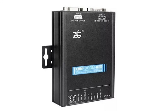


How to quickly implement CAN to CAN FD upgrade?
The rapid development of autonomous driving technology, the CAN bus in the vehicle can not meet the data throughput and transmission speed requirements, CAN FD technology is gradually replacing the existing network, in order to further understand CAN FD, this article will The practical application of the product introduces the upgrade and advantages of CAN FD.
With the rapid development of automotive electronics and industrial automation, the number of devices and the amount of data on the CAN bus have increased greatly. This has made the traditional CAN bus more and more incapable of transmission rate and bandwidth, so CAN FD was born.
So how do you implement the CAN to CAN FD upgrade?
First, the application of CANFDCOM
The CANFDCOM-100IE intelligent protocol converter can quickly connect RS-232/485/422 communication equipment to the CAN (FD)-bus field bus. The physical diagram is shown in Figure 1. The converter supports a serial port baud rate of 1200-921600bps and a CAN (FD)-bus communication rate of 50k-5Mbps.
Figure 1 CANFDCOM-100IE physical map
CANFDCOM-100IE is widely used, such as coal mine remote communication, PLC equipment networking, CAN (FD) industrial automation control system, existing RS-232/485/422 equipment connected to CAN (FD)-bus network.
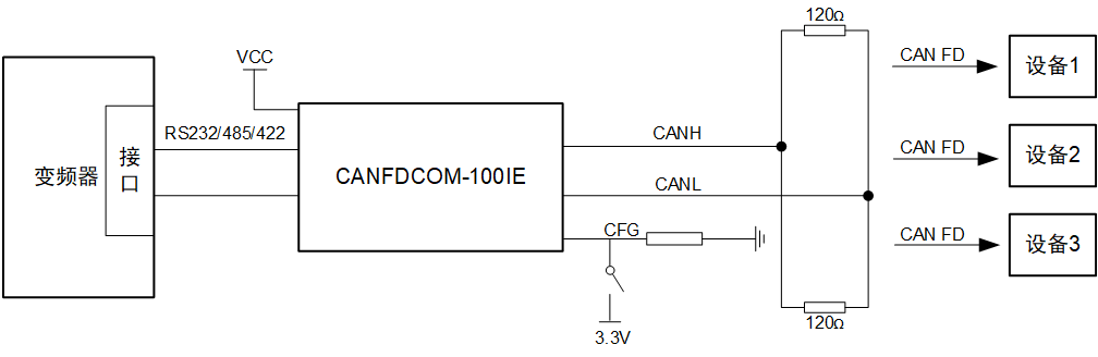
Figure 2 device connection circuit diagram
As shown in Figure 2, the inverter usually has an RS-232/485 interface, which can be quickly connected to the CAN (FD)-bus network via CANFDCOM-100IE serial to CAN (FD) to achieve CAN (FD). ) Send and receive messages.
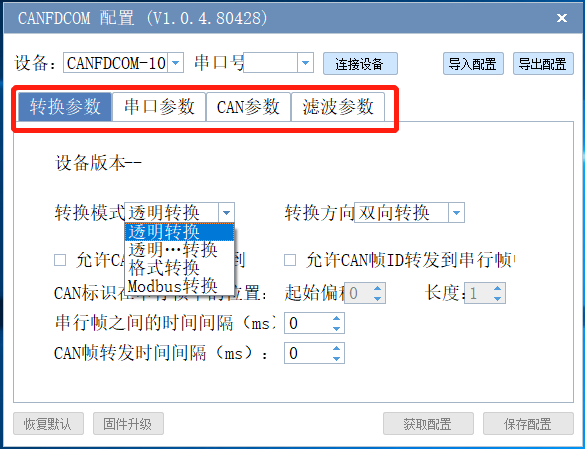
The converter supports four conversion modes: transparent conversion, transparent tape identification conversion, format conversion, and Modbus conversion to suit different user needs. At the same time, configuration software is provided, and the operating parameters of CANFDCOM-100IE can be flexibly set. As shown in Figure 3.
Figure 3 CANFDCOM configuration interface
CANFDCOM can also be connected to the PC end, and the other end is connected to the CAN (FD) network to transmit and receive serial frames and CAN (FD) messages.
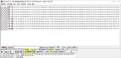
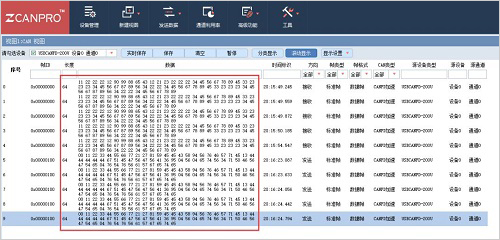
After the parameter configuration is completed, use the serial port assistant to send the serial frame to CAN (FD) message, as shown in Figure 4. CAN (FD) frame information can be observed with the ZCANPRO tool, as shown in Figure 5.
CANFDCOM-100IE supports ISO standard CAN FD and BoschCANFD standards. Each interface has an independent 2500VDC electrical isolation protection circuit, which prevents the interface card from being damaged due to ground circulation and enhances the reliability of the system in harsh environments.
Figure 4 serial frame transceiver interface
Figure 5 CAN FD frame information interface
Second, the application of CANFDSM
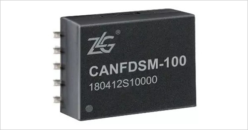
CANFDSM-100 is a serial-to-CAN (FD) module with a built-in microprocessor. The physical diagram is shown in Figure 6. It can be easily embedded in a device with a UART interface, as shown in Figure 7.
After adding a CAN (FD) transceiver, data communication between the UART device and the CAN-bus network is implemented.
Figure 6 CANFDSM-100 physical map
Figure 7 CANFDSM-100 renderings
Use the MCU to connect to the CANFDSM-100, as shown in Figure 8, where the LPC54616 is an LPC54000 series microcontroller from NXP. When the CFG pin is closed, it is used to configure the module. It is recommended to use the AT command in the configuration mode. The CAN (FD) interface uses the CTM3MFD isolation module, which makes it easy to connect the user's MCU to the CAN FD network.
The CAN controller is integrated inside the CANFDSM. The CAN controller is the core component of the CAN-bus device. It integrates all the functions of the data link layer in the CAN specification and can automatically resolve the CAN-bus protocol.
Figure 8 device connection diagram
However, CAN FD and traditional CAN are not much different in practical applications, cable selection, topology selection, bus layout, etc. are similar. The CAN transceiver is a level shifter that converts the logic level of the CAN controller to the differential level of the CAN bus.
Third, there are two options for implementing CAN transceivers.
1. Adopt CAN transceiver IC;
2. Use CAN isolation transceiver module.
In some cases where interference is severe, isolation is still essential. Isolation can avoid potential high voltage hazards, eliminate ground potential differences and ground loops, thus greatly improving the reliability of communication.
ZLG Zhiyuan Electronics' CAN FD isolated CAN transceivers CTM5MFD and CTM3MFD are compact and can support 5Mbit/s transmission rate. It is an ideal solution for CAN FD isolation applications. The selection of CAN FD isolation transceiver is shown in Table 1.
Table 1 CAN FD Isolated Transceiver Selection Table
Advantages of CAN FD
CAN FD inherits the main features of the CAN bus, improves the network communication bandwidth of the CAN bus, improves the error frame miss detection rate, and maintains most of the software and hardware of the network system, especially the physical layer. The CAN FD protocol is a new upgrade to the CAN-BUS protocol to meet higher bandwidth and data throughput.
The CAN FD rate consists of two segments. The arbitration segment and the ACK segment follow the CAN2.0 specification. The maximum rate is 1 Mbit/s. The middle data segment can be accelerated, which can reach 5 Mbit/s or even higher.
CAN FD greatly complements the length of the data field. The data length code (DLC) can transmit up to 64 bytes of valid data. This means that CAN FD has a higher effective transmission load;
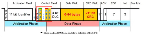
The CAN FD data frame newly adds the FDF bit, the BRS bit, the ESI bit in the control field (the FDF bit judges the message type, the BRS bit indicates the bit rate conversion, and the ESI bit indicates the error state), as shown in FIG. 9;
CAN FD changed the CRC algorithm, that is, the CRC is calculated by the bit stream with padding bits, which improves the error frame miss detection rate.
Figure 9 CAN FD standard frame
to sum up
1. To achieve a fast upgrade of CAN FD, you first need to use an MCU or controller that supports the CAN FD protocol, and also select a new network debugging and monitoring tool;
2. Transceivers that support higher transmission rates are required. If the upper limit rate of the designed CAN FD node is 5 Mbit/s, the transmission rate of the transceiver must also reach this value. The CAN FD isolated CAN transceivers CTM5MFD and CTM3MFD are ideal solutions for CAN FD isolation applications.