Blind Blade Making Machine,Sigma Profile Roll Forming Machine,Purlin Molding Machine Unovo Machinery Co., Ltd. , http://www.jsformingmachine.com
1. System Design 1.1 Network Architecture and Protocol The network topology mainly describes the connection mode of network nodes. The collection of human physiological parameters is small, sensor nodes are concentrated, and communication between nodes is generally not required. Based on these characteristics, a star network topology can be used. In the star topology, each branch node is connected to the central node in a point-to-point manner. When a large number of communications are performed between the central node and the branch node, the use of a star topology is most effective. Its advantages are that it can concentrate resources, the network is easy to manage, the coverage is concentrated, and the routing algorithm is relatively simple. The problematic nodes are easily isolated by the central node without affecting the performance of other nodes.
In wireless sensor networks, the MAC (Medium Access Control) protocol determines the use of wireless channels, and allocates limited wireless communication resources among sensor nodes, which has a great influence on the performance of the sensor network. This is to ensure the low power consumption of wireless sensor networks. One of the key network protocols. In human body physiological parameter acquisition applications, sensor nodes periodically collect data, power supply often uses small button batteries, and the central node generally has sufficient power supply, so the CSMA/CA (CarrierSenseMultipleAccesswithCollisionAvoidance) control protocol is used. The central node does not close the radio module and continues to receive signals. The sensor node samples and sends data at regular intervals. When the data needs to be sent, the RF module is turned on. The channel is first intercepted. If the channel is occupied, the channel is reclaimed for a random period of time before continuing to listen. If the channel is not occupied, the sensor node sends the data. After the data is confirmed, the RF module is turned off and the MCU enters sleep mode and waits for the next timing trigger.
1.2 RF Transceivers and Network Operating Systems Sensor nodes require small size, low power consumption, data processing, and wireless transceivers. TI/Chipcon's CC2430EM evaluation board is used as a wireless transceiver module, and sensor circuits are designed as needed. Ports P0.1~P0.7, P1.0~P1.7 and P2.0~P2.2 of the CC2430 evaluation board can be connected to the sensor circuit for control. Chip CC2430 embedded CC2420 RF transceiver and 8051MCU, including 12bit analog-to-digital converter, 4 timers, 32kHz crystal sleep mode timer, hardware support CSMA/CA, supply voltage 2.0V ~ 3.6V, in the power-down Current consumption is only 0.5μA in mode and can be awakened by an external interrupt or real-time clock. A wireless sensor network can be viewed as a computer system consisting of multiple CPUs with limited energy, storage space, and processing power. These CPUs are independent and work together. To facilitate software development and maintenance and improve software development efficiency, TinyOS embedded operating system is used. TinyOS is a component-based operating system designed specifically for embedded systems. It is mainly used in wireless sensor networks and is implemented in nesC language. It uses lightweight thread technology, active message communication technology, event-driven mode, and componentized programming. . Using this operating system can improve the CPU usage. Under the schedule of TinyOS, all tasks associated with communication events can be quickly processed when the event is generated. After processing is complete and there are no other events, the CPU will go to sleep.
1.3 Node Design Figure 1 shows the human body physiological parameter acquisition network structure diagram. To improve portability, the PC can be replaced with an embedded device. Each sensor node in the figure regularly samples and sends data. The central node receives the data and sends it to the PC through the serial port for display and processing. 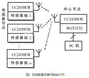
There are two types of nodes: sensor nodes and central nodes. In the TinyOS environment, the programming language is nesC. In order to support the componentized programming model, the nesC language introduces the concept of interfaces and components. Interfaces are function declarations with similar or related functions, named as commands or events depending on the direction of the call, and implemented in components that provide or use the interface. Components include accessories and modules that are responsible for connecting different components through an interface and the module provides the code implementation required by the program. For sensor nodes, hardware driver components need to be designed for different sensors, and combined with existing intermediate components (such as system components, power management components, A/D conversion components, timer components, radio frequency components, etc.) to design the configuration components of the application layer. And module components. The following describes the design method using a temperature and humidity sensor node as an example. The temperature and humidity sensor uses SHT10 from SENSIRION of Switzerland.
The components of the temperature and humidity sensor node are connected as shown in Figure 2. The small rectangle is the interface used and provided by each component. The direction of the arrow indicates the direction of the command. Because all sensor nodes have the functions of timing sampling, data processing, protocol data transceiving, radio frequency module and MCU power management, the sensor-related operation here is to design a component SHT10_C separately, with different types of sensor components in the top-level accessories. Connect to achieve the function of each sensor node. SensorNet_C, an intermediate component, is designed to be independent of sensor operation and other application-related functions. It is connected to the lower components McuSleepC, CsmaC, and CC2430ActiveMessageC to implement MCU power management, CSMA protocol, and RF module control. The accessories SHT10_C and SensorNet_C only provide connection relationships between components, and their implementation is performed by SHT10_M and SensorNet_M, respectively. When the Send.send() command is used to send data, the clean channel assessment is performed first. If the channel is occupied, it needs to be backed off for a period of time. The backoff time is generated by a random function that generates a random number between 1 and 31, multiplied by a given initial value (here set to 160 μs, or 10 symbols). The initial value can be adjusted according to the number of nodes in the network. When the number of nodes is smaller, the initial value is smaller, and if not, the value is increased. The top-level configuration component program of the temperature and humidity sensor node is as follows: 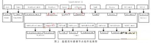
configurationSensorNodeSHT_C{
}
Implementation{
componentsMainC;/*TinyOS2 main module, used here to associate system startup*/
componentsnewTimerMilliC()asTimerC;
componentsSensorNet_C;/*RF module, CSMA protocol and MCU power management control configuration component*/
componentsSHT10_C;/*Temperature and humidity sensor SHT10 configuration components*/
componentsSensorNodeSHT_M;/* Top level module component*/
SensorNodeSHT_M.Boot->MainC.Boot;
SensorNodeSTH_M.Timer->TimerC;
SensorNodeSTH_M.RFControl->SensorNet_C;
SensorNodeSTH_M.AMPacket->SensorNet_C;
......
SensorNodeSTH_M.Send->SensorNet_C;
SensorNodeSTH_M.SHT->SHT10_C;/* Interface STH connection */
}
In the accessory SensorNet_C, the radio function provided in the module component CC2430 ActiveMessageP is used via the connection component CC2430ActiveMessageC. The CC2430ActiveMessageP is the top-level component in the RF stack and provides a single-hop communication implementation. The MCU power management function in the module component McuSleepP is used to connect the accessories McuSleepC to implement functions such as sleep, timing, and startup of the MCU to reduce power consumption of the node. You need to implement the events McuSleepControl.beforeSleep() and McuSleepControl.afterWakeup() in the upper-level component SensorNet_M of the McuSleepP component to protect and restore the state before and after sleep.
The temperature and humidity sensor SHT10 has a two-wire serial interface that outputs calibrated digital signals. The interface SHT defined here for the SHT 10 is as follows, and the commands defined by the interface need to be implemented in the module component SHT10_M.
interfaceSHT{
Commanderror_tread();/* is implemented in sensor module component STH10_M*/
eventvoidreadDone(error_tresult,uint16_ttemperature,uint16_thumidity);/*implemented in the top module component SensorNodeSHT_M*/
}
The central node implements RF data reception, and then sends the data to the PC through the serial port. Its top-level configuration file is as follows:
configurationCenterNode_C{
}
Implementation{
componentsCenterNode_M;/* Top level module component*/
componentsMainC;
componentsCC2430ActiveMessageCasActiveMessageC;
componentsABSC;/*serial communication control component*/
CenterNode_M.Boot->MainC.Boot;
CenterNode_M.RFControl->ActiveMessageC;
CenterNode_M.AMPacket->ActiveMessageC;
CenterNode_M.Packet->ActiveMessageC;
CenterNode_M.Receive->ActiveMessageC.Receive;
CenterNode_M.ABS->ABSC;
}
2. The sensor node power consumption calculation collects human physiological parameters. Especially in outdoor applications, low power consumption is very important for battery-powered sensor nodes. The power consumption of the sensor node in this design is calculated by the following method in reference [6]. Using a 3.3V DC power supply, a 1% accurate 10Ω resistor is placed in series with the CC2430EM, and the current in each period of a sampling cycle is calculated by measuring the voltage drop across the resistor. Sampling period T = 10s, CC2430 RF output power is set to 100%, Figure 3 is the use of oscilloscope TPS2024 when the sensor node to send data to obtain the voltage waveform changes at both ends of the resistance, horizontal direction 2.50ms / div, vertical direction 100mV / div . Table 1 shows the current consumption during the activity. 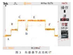
Low-power mode time within a sampling period T (sections A and G, CC2430 in PM2 mode):
TPM2=T-Ton=10000ms-20.45ms=10451.65ms
Current consumption in low power mode (CC2430 in PM2 mode):
0.0005mA×10451.65ms=5.2258mA·ms
Total current consumption during one sampling period T:
472.1mA·ms+5.2258mA·ms)/(3600000ms/h)=1.326×10-4mAh/10s
Hourly consumption current: 1.326×10-4×360=0.04774mA
Assuming the use of a 60mAh coin cell, the available time is: 60mAh/0.04774mA=1256h≈52 days.
In this paper, the core node and sensor node program based on TinyOS are designed using nesC language, and a star wireless sensor network using CSMA/CA protocol is realized. Taking the temperature and humidity data acquisition as an example, a sensor node using temperature and humidity digital sensor SHT10 is designed. . When the sampling period is 10s and 60mAh battery power is used, the sensor node can last 52 days. This design can meet the needs of wireless, portable, low-power acquisition of human physiological parameters. With the modular programming language nesC, development efficiency is increased and it is easy to expand. The research and design methods described in this article can be used in related applications.
Application of Wireless Sensor Network Technology in Human Body Parameters Acquisition
The collection of physiological parameters refers to the measurement, processing and transmission of certain physiological parameters when a person is still or active in a particular environment. The technology has a wide range of applications, such as medical, health, sports, military, and apparel comfort evaluation. The method for realizing the physiological parameter acquisition is to place the sensor in a corresponding part of the human body, and transmit the data collected by the sensor to the terminal for processing in a wired or wireless manner. In the use of cable transmission methods are sometimes limited, so it is necessary to study the use of wireless data transmission methods. For example, in the appraisal of clothing comfort, the main methods are: measuring the temperature and humidity of the human body in a real environment; and measuring the temperature and humidity of a real or pseudo human body in a simulated environment (artificial climate room), and Subjective and objective evaluation. When carrying out dynamic experiments on the human body in a real environment, wireless data acquisition and transmission will bring great convenience. Wireless sensor network technology has developed rapidly. The application of this technology to human physiological parameters has been applied in the country. For example, reference [2] proposes the application of wireless sensor network based on Zigbee technology in remote home monitoring. Reference [3] ] The application of wireless sensor technology in medical monitoring is proposed. This paper will analyze and design the human body parameter acquisition from the aspects of hardware and software platform selection, network architecture, MAC layer protocol, node low-power design and other aspects of the wireless sensor network node.