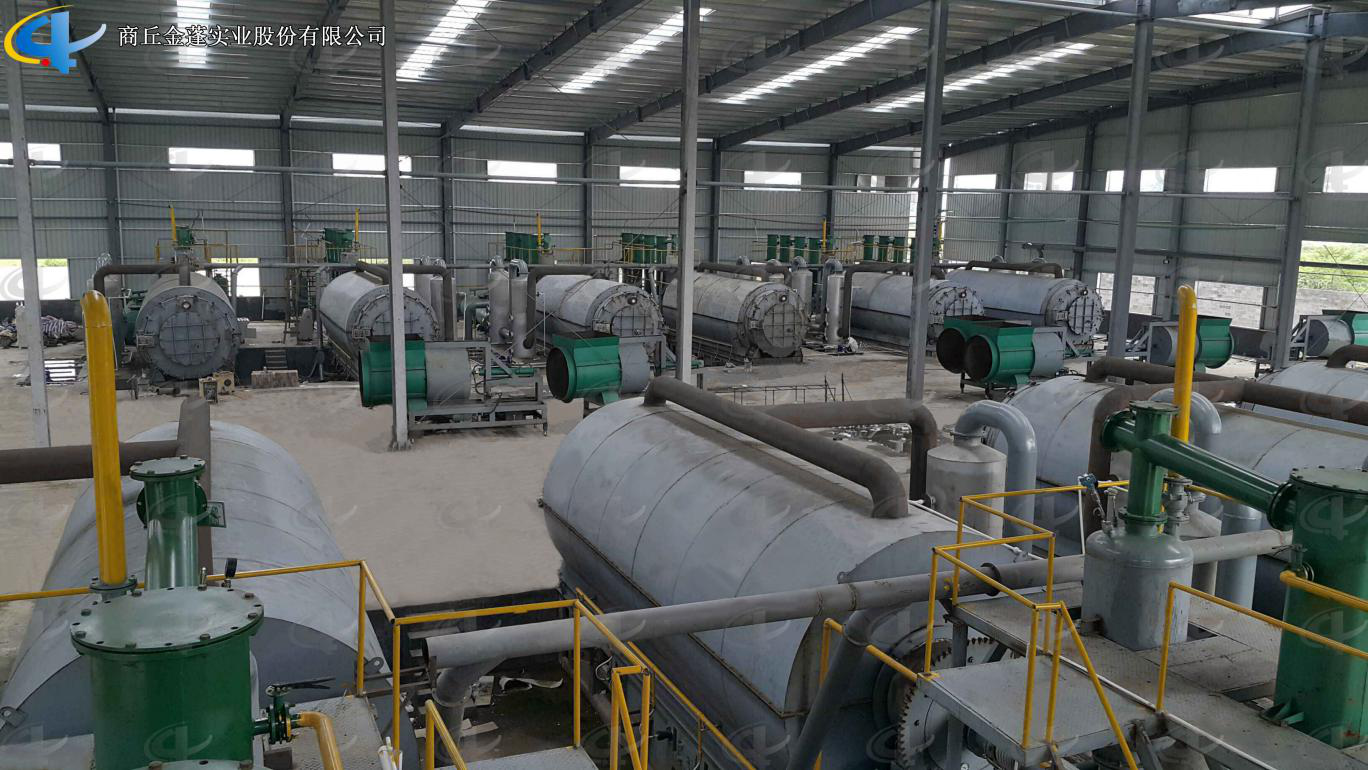
Semi-continuous Waste Tyre Pyrolysis Plant
Pyrolysis Plant is used for recycling waste tire, waste plastic, waste rubber to fuel oil. According to the actual situation in every country and district, we developed different models of Batch Pyrolysis Plants for waste tires, rubber and plastic with daily capacity 5 -10 tons.
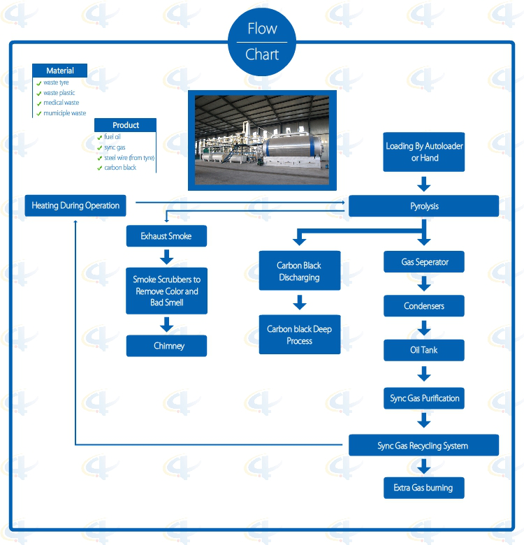
Flowchat of Batch Waste Tyre Pyrolysis Plant
Advantages of Batch Waste Tyre Pyrolysis Plant
1. Full open door design: Speedy loading in and steel pulling out; Easily cooling down after one batch finished, saving time; No leaking with special high temperature flexible graphite packing.
2. Unique Craft Condensers: High condensing efficiency with more oil output. Good quality oil, longer lifetime, and easy to clean.
3. National Patent Unique Smoke Scrubbers: More efficient removal of the acid gas and dust of the smoke by neutralization, purification and absorption, environmental friendly without pollution.
4. National Patent Carbon Black Discharging System: Speedy fully enclosed Auto-discharging under high temperature, avoiding carbon black pollution, saving time.
5. Automatic Submerged welding technology, ultrasonic nondestructive testing, both manual and the automatic safety devices.
6. Sync Gas Recycling System: Fully burned after recycling and utilization, saving fuel and preventing pollution.
7. Direct Heating System: Enlarging heating square to lengthen the lifespan of the reactor and easy to control the temperature.
8. National Patent, unique heat insulation shell; high efficiency temperature keeping, excellent energy-saving effect.
Technical Parameter of Batch Waste Tyre Pyrolysis Plant
NO.
ITEM
PROJECT
1
Equipment Model
XY-7
XY-8
2
Door Model
Full Open Door
Full Open Door
3
Suitable Raw Materials
Rubber/Plastic Products
Rubber/Plastic Products
4
Structure
Horizontal Type Revolves
Horizontal Type Revolves
5
Reactor Size
Φ2200*6000mm Φ2600*6600mm
Φ2200*6000mm Φ2600*6600mm
6
Capacity for One Batch
5-6Mt; 8-10Mt
5-6Mt; 8-10Mt
7
Oil Yield of Tires
40%-45%
40%-45%
8
Work Pressure
Normal Pressure
Normal Pressure
9
Reactor Rotation Speed
0.4R/M
0.4R/M
10
Fuels Choice
Coal, Wood
Coal, Wood, Gas, Oil
11
Power
18KW/H
18-25KW/H
12
Cooling Method
Water Cycling
Water Cycling
13
Type of Drive
External Annular Gear
External Annular Gear
14
Heating Method
Direct
Direct
15
Type of Installation
With Foundation
With Foundation/Integrated Base
16
Noise dB(A)
≦85
≦85
17
Operation Mode
Intermittent Operation
Intermittent Operation
18
Total Weight(MT)
25-40
25-40
19
Installation Space Required
30m*10m
30m*10m
20
Manpower
3~4/batch
3~4/batch
21
Shipment
Ф2200×6000=1*40HC+1*40FR
Ф2600×6600=2*40HC+1*40FR
Ф2200×6000=1*40HC+1*40FR
Ф2600×6600=2*40HC+1*40FR
Semi-Continuous Waste Tyre Pyrolysis Plant Semi-Continuous Waste Tyre Pyrolysis Plant,Newest Semicontinuous Used Tyre Pyrolysis Plant,Semi-Continuous Rubber Pyrolysis Plant,Practical Semi-Continuous Waste Tyre Pyrolysis Plant Shangqiu Jinpeng Industrial Co., Ltd. , https://www.recyclings.nl
1. When the pressure transmitter diaphragm and gauge are crimped, the uneven surface of the diaphragm needs to be cut. At this time, it will produce banded chips, that is, the surface is smooth, but the internal is very hard, generally only need to Speed ​​up when cutting and when larger tools are used.
2. Nodular chips, the outer surface is generally serrated, mainly due to the special nature of the head. Because pressure transmitters have different meter housings, the cutting tools used in manufacturing are also different. If the transmitter's cutting speed is too low at this time, it will produce nodal chips.
Then how to control these chips in the production process, why do you see the surface of the pressure transmitter housing is smooth, there is no pit due to chipping, because the cutting control technology is good.
1. A good smooth cutting groove must be used in the cutting of the shell so that the smooth radius groove can well control the flow force.
2, is the corresponding different original shell on the use of different angles.
3, if this shell material is not suitable for cutting, it needs to be replaced, so as to avoid pressure transmitter shell fracture too much, affect the quality.
Aeronol Fluid Control (Shanghai) Co., Ltd. is currently a number of well-known brands abroad, focusing on the marketing and sales of imported sensors, instrumentation, and adhere to the development direction of multi-species, multi-brand, differentiated and enthusiastic service. Welcome customers to negotiate.


Elorang describes chip types and control methods for pressure transmitters
After years of research, the pressure transmitter has a certain fracture at the time of manufacture. The larger the index, the easier it is for the cutting to break. Because the cutting conditions of the pressure transmitter are very different, it is at the sensor joint. The cutting process produces a wide variety of different shapes of chips. These different cuttings represent the pressure transmitter's tightness. Here's a detailed analysis of which chips will be produced. .