Introduction: Today, we should introduce in detail the test setup method of the E5071C network analyzer: 1. Frequency setting: Press Start on the instrument panel as the start frequency and Stop as the stop frequency. If we want to measure 2.4G to 5.8G, we first press Start to set it to 2.4G, then press Stop to set it to 5.8G.
The windshield wiper transmission is an integral component of your vehicle`s windshield wiper system. It is a mechanical device made up of multiple linkages that connect the Wiper Motor to the two wiper arms, transferring the power generated from the rotational movement of the motor when it is activated by the wiper controls into the sweeping back and forth motion of the windshield wiper arms which the blades that clean the windshield are attached to. The wiper transmission helps the wiper motor and arms work together without having to hit each other. The multiple sections of linkage are joined and held together by rivets, while bushings are mounted to the Wiper Linkage arms and act similarly to bearings. Together, they make it possible for the different sections of the wiper linkage assembly to rotate and pivot.
On most vehicles, the wiper linkage assembly is located under the cowl at the base of the windshield and hidden out of view. This protects the mechanism from being exposed to outside elements and allows for it to operate quietly when being used.
Windshield wiper transmissions are the most common failed parts of the wiper system and can require replacement for multiple reasons. A Windshield Wiper Linkage assembly will make an annoying clunking or squeaking sound when they wear out from prolonged use over time. Turning on frozen wiper blades without properly loosening them from an icy windshield during the cold winter season is a notorious and common cause of damage to wiper systems; this forces the wiper motor to put excess stress on the wiper linkages and arms. This stress can cause plastic connectors to break, pivot points to elongate, and knurled wiper studs to round off. Heavy snow and ice can also force the wiper motor to put excess stress on the linkages and wiper arms, as can large amounts of dirt, causing a similar outcome.
A broken or damaged windshield wiper linkage assembly can cause the wipers to not work or work incompletely, which can be quite hazardous for you and other drivers around you. Therefore, if your wiper transmission has failed, obtaining a replacement and installing it quickly is highly recommended.
To Shave Wiper Linkage,Fiat Stilo Wiper Linkage,Broken Windshield Wiper Linkage,Front Windshield Wiper Linkage COMOTECH ASIA PACIFIC (HANGZHOU)CO.,LTD , https://www.capwiper.com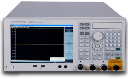
2. Transmission and reflection test function setting: After opening Meas in the instrument panel, the display menu will have S11 S21 S12 S22 (S11 S22 is reflection and S21 S12 is transmission) Note: VSWR and return loss are in the reflectance test. , That is to say tested in S11 or S22, S11 and S21 are the first test port test, and S22 and S12 are the second port test.
3. VSWR and Insertion Loss Test Settings: After the panel selection button Format is opened, there are several indicators of the test products in the display menu. We can choose according to the test indicators needed by our products, such as the more commonly used SWR (standing wave Ratio), Log mag (insertion loss)
4. Multi-window and multiple test line settings: After the panel select button Display is opened, there will be many functions in the display menu. We use the Num of Traces to set to 2, and two test lines will appear in the display. One is yellow and the other is blue, but now both test lines are in a test window. We can also separate the two test lines in two test windows for testing; we can display the selection window in Allocate. .
5. Change two test settings: Use the Trace key on the panel to switch between the yellow and blue line settings.
For example: to see the display Tr1 S11 yellow line settings, select on the panel, Format inside select SWR (Stop wave ratio test) At this time the yellow line is to test the VSWR, we press the Trace button to set the blue line test Tr2 S21 Prev Press Format selection Log mag (insertion loss test) At this point we can now measure the VSWR and insertion loss of our product at the same time.
6. Instrument calibration method: select the Cal display inside the panel keys; Calibrate press 2-Port Cal in the next step; Next enter into the corresponding calibration after the reflection, such as Open (Short) Short circuit) Load PORT1 port and PORT2 port to confirm the end of school, if the end of school display will be ticked; next press and then press the screen menu to return the next step by Transmission next step on the test line to put PORT1 and a PORT2 two ports connected; the next press Thru; the next step to press Return: the next step by Isolation; PORT1 port and PORT2 two (optional) connection disconnected; the next step by Port1-2Isol; the next step by the Return; Press Done in one step; calibration is complete! At this point, connect PORT1 and PORT2, the yellow line should be at the bottom of the display, the blue line should be in the middle, turn the cursor on and test out the indicator yellow line should be about 1.020, the blue line indicator should be -0.0005 or so.
7. Cursor opening method: After selecting the button Marker on the panel, the display screen will have multiple choices from 01-08. We can select one or more test cursors to read our product indicators.
What is a windshield Wiper Transmission Linkage and where is it located?
How do I know if my windshield wiper transmission needs to be replaced?